Commodore 64, the best selling personal computer in the world is back!
15 years ago a kid from the neighborhood came to me and asked if my dad can fix his computer. My dad has a computer and printer repair shop. When the kid brought his computer, it was just a keyboard. I told him that he needs a case and a monitor for this to work but he insisted that he used to just plug in the "keyboard" into the TV and played video games on it, until it stopped working. Sadly my dad was not interested in fixing the keyboard, but he told me that its a very old computer named Commodore.
More than a decade later I was sending Instagram reels to my father in law about retro computers and he said that he has a Commodore 64 lying around in his basement and I can have it if I'm intereseted. So here I am, with a machine from 1982, and sheer curiosity and excitement to get it to work. Even though C64 predates me by almost 10 years, the off white/beige (RAL1019) color of the case on this machine reminds me of the old dot matrix printers and my very first computer Intel i486. In this blog post I'll walk you through the steps that I have done and the plans that I have. Hoping that this either refreshes some old memories for you, tickles your curiosity, or helps you setup your old C64.
What is Commodore64?
This 8-bit machine which takes its name from its 64kb memory capacity made it back to the news lately with an announcement to release a new and refreshed version of C64. "A return from a parallel timeline where technology stayed optimistic, inviting, and human, the Commodore 64 Ultimate blends classic form with modern function. It’s the first official Commodore 64 in over 30 years, featuring several new tricks, and available for pre-order exclusively on Commodore.net."
You can write programs for C64 mainly in Assembly and BASIC. And the default interface which drops you straight into the CLI allows you to write BASIC right off the bat. I already learned a few commands and vibe coded my first basic program. Printing hello world in a for loop. C64 does not have a sleep command but the processor is so slow that looping 1000 times introduces a noticeable 0.5 second delay.
10 PRINT "HELLO WORLD"
20 FOR I = 1 TO 1000: NEXT I
30 PRINT CHR$(147)
40 GOTO 10
After the initial experience with the basic program, I read a few of the posts on r/c64 and noticed a few things:
- The PSU (Power brick) of C64 is referred to as the brick of death. Apparently these units which are also 40ish years old at this point are prone to failure. And when this happens the PSU let's through a higher voltage than it should and fries the chips on board. So the first action item is to replace this with a modern PSU.
- The diskettes used in these machines are quite hard to find. The ones available on ebay are quite pricey. But the saving grace is that there exists a few projects out there that simulate/emulate the disk drive and allow you to run the images for games and programs from an SD card. SD2IEC and pi1541 are two options.
Connecting C64 to a display
I skipped over the part where I plugged my c64 to a display. I mean what is there to discuss about it right? Well in 1982, HDMI was not a thing. The options for C64 are RF or Composite. I'm old enough to have used the red-yellow-white cables to connect stuff to the TV. So I quickly ordered a composite to 8 pin DIN cable off of amazon. But there was a problem, the cable wouldn't fit in the port!
As it turns out, C64s went through many revisions. These revisions are not explicitly called out outside of maybe the serial number or a label in the back. In my case, I had one of the first versions of C64 with 5 pin DIN display port.
The community around C64 is very helpful and active. There's forum and reddit threads discussing the common challenges and there's a good number of youtube videos out there. So we can either diy the port or find a vendor that sells them for a reasonable price. In my case I went with a $15 cable that worked well. I do get the jail bars and there's options with better output quality. 5 Port DIN to Composite Cable
But my main goal at this point was to get the machine running and verify that it works. A more expensive option would have been RGBtoHDMI or one of the manufactured adapters such as RetroTINK. I wanted to keep the cost manageable while also maintaining the spirit of curiosity and diy. At the end of the day if one really just wants to run C64 games there's free web based emulators out there.
With the cable situation figured out, I plugged in the C64 to my TV and voila. I got the beatiful blue screen.
A look inside C64
Let's take a peek inside a C64 and admire its simplicity. Commodore 64 motherboard
The soldering looks like it was done by hand. I certainly recall the looks of the old, bulky and non-surface mounted components from the old electronic devices. The cables going into the keyboard are held in place with a piece of packaging tape xD. Wires going to the keyboard secured with tape
Similar to the ports, there's a few different variations of the board and this one is certainly not the most common one you'd find online in the diagrams and pictures. c64 wiki is a great place to read more about the motherboard and its components.
Fixing the brick of death (Power Supply)
Now that I know the machine is working, let's listen to everybody out there telling us not to use the old PSU.
So now the research began for the options for a new PSU. A few enthusiasts around the world have made replacement PSUs ready for purchase. c64psu.com is a recommended vendor from Poland. retropower is another good option with US shipping. Also available on Amazon. Unfortunately these units cost about $70 dollars. So I looked into diy options.
https://www.c64-wiki.com/wiki/Power_Supply tells us that the common failure is mainly due to the 5v output spiking above 6v and frying the RAM. Further down on the same page you can see that the bulky PSU is essentially taking the 110v AC input and outputting 9v AC using a simple step down transformer and a small circuit for 5v DC. And the DC circuit is the failure prone one. 12v AC to 5v DC converter circuit
Following the same theme of C64 variations over time, there's a few different types of PSUs out there. Many of the older ones fix the transformers in place with epoxy. It's possible to crack them open and replace the parts, but its certainly going to be a headache.
Luckily I had one of the units without epoxy. So it makes sense to try to fit the new circuit inside the existing shell.
We can either find or build the circuit for 5v DC. This part is not hard given that most power adapters and phone chargers these days output 5v and I certainly have more than a few extra phone chargers lying around.
Finding a transformer to output 9v while not paying 20+ dollars or shipping it from China is not trivial. If it wasn't for tariffs I would just get one from AliExpress but these days I'm not sure what the shipping and tax is like.
The most simplistic and safest option here is to get two separate power adapters for AC and DC such as these ones from Amazon:
- 5v DC (1.5A+) - plenty of options: https://www.amazon.com/Adapter-Regulated-Switching-Interchangeable-Equipment/dp/B0B7RWFH98/
- 9v AC from Jameco: https://www.amazon.com/Reliapro-ADU090150A2231-Adapter-Transformer-Straight/dp/B00B886CWS/
You would plug them in and solder the output to the correct pins in the DIN port:
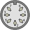
| Pin | Voltage / Current | Description |
|---|---|---|
| 1 | Ground | |
| 2 | Ground | |
| 3 | Ground | |
| 4 | NA | Not Connected |
| 5 | 5v / 1.5A | |
| 6 | 9v / 1.0A | Alternating phase 1 |
| 7 | 9v / 1.0A | Alternating phase 2 |
Here's a video explaining this process: https://www.youtube.com/watch?v=wWOU2sZv_ng
The route that I chose was to only replace the 5v circuit with a regular mobile charger. In my case the 5v circuit was taking a 12v AC input and not directly the 110v. But given that my phone charger expected 110v, I bypassed that section and routed the input directly to the probes of the charger. Then I used my multimeter to find the correct wires in the USB cable that outputted 5v DC and soldered them to the wire going to the DIN port.
Then I secured the charger inside the PSU using double sided tape, double checked the voltage from the pins and plugged it into my C64. Modified power supply
Next, we need to load programs into our C64. For that I setup a pi1541 emulator and I am in the process of designing a 1541 disk drive replica case for my Raspberry Pi. I will cover the rest of my journey in a follow up blog post.
I'd close this post with a picture of Lina enjoying 8-bit theme song from the Ghosts and Goblins. Lina ejoying Ghosts & Goblins